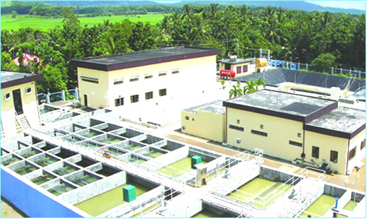
To serve our best, Metro Roxas Water District (MRWD) continuously improve and maintain its transmission lines, distribution networks, reservoirs and treatment plant. The newly constructed 30,000 cu.m. per day capacity Water Treatment Plant in Paslang, Brgy. Salocon, Panitan, Capiz is included in the Metro Roxas Water Supply System and Improvement and Expansion Project (MRWSSIEP) and continue reading : Water Treatment Plant in Paslang, Brgy. Salocon, Panitan, Capiz
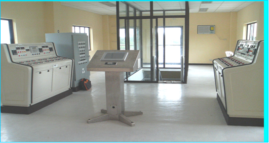
The State of the Art Control Room
Three (3) parameters to be considered before backwashing; Filter Runtime, Loss of Head and Turbidity. The 2 Magelis Terminals located at the 2 Filter Consoles monitored the Runtime of each Filter from the time it was last backwashed, the same data is transmitted to the OIT. Installed to each Filter Basin are the Strainer and continue reading : The State of the Art Control Room
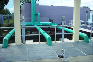
The Intake Structure (IS)
The system starts in the IS where raw water from Panay River enters through a coarse bar screen to prevent large debris and through a fine screen to further prevent entrance of smaller solids before it is pumped by 2-duty & 1-standby, 3 – 75 Hp Submersible Pumps, to the Sand and Grit Removal Chamber continue reading : The Intake Structure (IS)
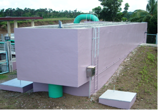
The Sand and Grit Removal Chamber (SGRC)
The SGRC acts as filter for the sand and silt and reduces raw water Turbidity by 10 to 20 percent. The Digital Conductivity Analyzer along with its Electrodeless Conductivity Sensor are installed at the SGRC to monitor the saline content of raw water and when the conductivity measures 2,000 micro Siemens/cm or more (too salty continue reading : The Sand and Grit Removal Chamber (SGRC)
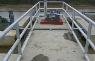
The Flash Mixing Chamber (FMC)
The raw water from the SGRC flows by gravity through a 600 mm steel pipe to the FMC equipped with 25 Hp Rapid Mixer to ensure vigorous homogeneous mixing of the raw water with the chemical reagents. Attached to the 600 mm steel pipe are the upstream and downstream sensors of Plant Influent Digital Flow continue reading : The Flash Mixing Chamber (FMC)
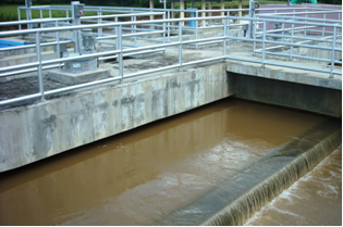
The Flocculation Tanks (FTs)
The chemically treated raw water passes through the first two parallel FTs where slow mixing occurs for further coagulation, it is then allowed to overflow to the second two parallel FTs mixed at a slower pace to allow flocs to agglomerate and to start settling down. The flocculated water is allowed to flow underneath the continue reading : The Flocculation Tanks (FTs)
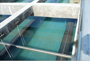
The Sedimentation Basins (SBs)
Tube Settlers are installed to increase the settling capacity of the SBs by reducing the vertical distance a floc particle must settle before agglomerating to form larger particles and by capturing the fine flocs that escaped the clarification zone beneath. Clarification Tract (Clari-trac) Systems are installed to collect settled sludge at the bottom of the continue reading : The Sedimentation Basins (SBs)
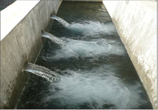
Clarifier Overflow Channel
Clarified water leaves the SBs through a submerged 8-300 mm black perforated PVC pipes installed above the tube settlers and allowed to flow to the Clarifier Overflow Channel where the water level is monitored by a Level Transmitter that transmits the signal to the OIT.
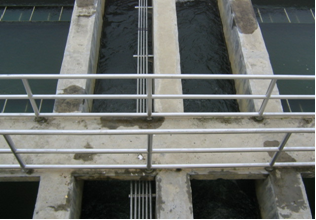
The Filtration Basins
Clarified water from the clarifier overflow channel is evenly distributed to the 4 gravity dual media filters at the Filtration Basins through a 4-350 mm steel pipe where the remaining colloidal particles are being filtered at the filtration chambers, which utilized 2 layers of filter media, the Anthracite over the Silica Sand. The HDPE Type-S continue reading : The Filtration Basins
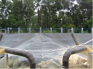
The Sludge Lagoon
The backwash wastewater flow by gravity into the sludge pit and as the water reaches the set water level, the 2-30 Hp Submersible Sludge Pumps automatically run and empty the sludge pit by transferring its content to the sludge lagoon. Backwashing can be performed in three (3) ways; Automatic, Semi-automatic and Manual. In Automatic mode, continue reading : The Sludge Lagoon


